그라운드 그리드 회로에 대한 이해
http://tubecad.com/2014/11/blog0312.htm
effective.
If there is a "real" grounded-grid amplifier, is there then an "unreal" grounded-grid amplifier? Yes, indeed, which is a nuisance and headache for someone like me. How so? I often receive e-mails that ask about the grounded-grid amplifier and I must figure out if they really mean the circuit shown below, which uses one triode, or the cathode-coupled amplifier that Bruce Rozenblit designed, which uses three triodes.
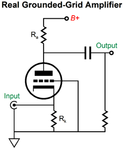
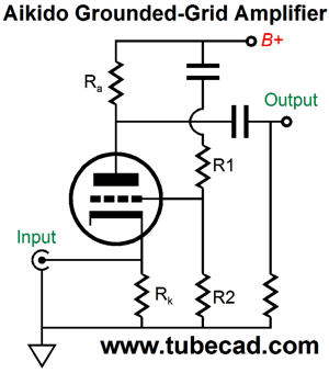
The real grounded-grid amplifier is a simple affair: the grid is grounded, if not directly to ground, at least AC "grounded" via a capacitor to ground; the cathode receives the input signal, either directly or via a resistor or capacitor or coil; and the output is taken at the plate, in the same as it is in the grounded-cathode amplifier, where the plate meets the plate resistor, Ra. The result is no phase inversion of the input signal and much higher high-frequency bandwidth, as the cathode is shielded from the Miller-effect capacitance by the grounded grid. Because of its better high-frequency response over the comparable grounded-cathode amplifier, the grounded-grid amplifier has found its widest use in radio designs. Indeed, its use in audio circuits has been rare, being limited by it comparatively low input impedance.
How low an input impedance? Where a grounded-cathode amplifier offers, at audio frequencies, an input impedance roughly equal to the resistor that connects the grid to ground, the grounded-grid amplifier's input impedance is equal to:
Zin = (Ra + rp) / (mu + 1) || Rk
where || stands for in parallel with, such that a || B equals (a x b) / (a + b). On the other hand, if the cathode resistor terminates into the signal source, rather than ground, then the formula is:
Zin = (Ra + rp) / (mu + 1) + Rk
One interesting feature of the grounded-grid amplifier is that it offers a slightly higher gain than the comparable grounded-cathode amplifier, as the cathode offer a slightly higher transconductance than the grid. Where the grid's transconductance is given by
Gm = mu / rp,
the cathode transconductance equals
Gm = (mu + 1) / rp.
Thus, the formula for the AC voltage gain of a grounded-grid amplifier is
Gain = (mu + 1)Ra / (Ra + rp),
assuming no series resistance. If there is a series resistance, Rs, then the formula becomes:
Gain = (mu + 1)Ra / [Ra + rp + (mu + 1)Rs]
This is the atomic grounded-grid amplifier, which then can be incorporated on more complex topologies. Since most small-signal triodes usually come in pairs, such as the 6DJ8, 6SN7, 12AU7…, we always face the problem of what to do with the second triode. Believe me, if the twin-triode tube did not exist, the SRPP would not be as popular as it is. (Having mentioned the darling topology of tube audio, I should, if only in passing, that the grounded-grid amplifier can be SRPP-ed by adding a second triode atop the plate resistor, which is just what Bruce Rozenblit did in his "grounded-grid amplifier.") The first obvious addition would be to follow the grounded-grid amplifier with a cathode follower, which would offer a low output impedance and shield the grounded-grid amplifier from the external load. I like this sort of arrangement, as I like the input stage to have the single task of providing gain and nothing else, while the output stage provides a low output impedance and big current deliveries, but no voltage gain.
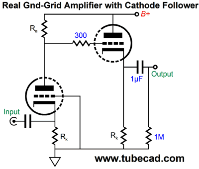
Note the addition of not only the cathode follower, but the input coupling capacitor. Since the triode is cathode biased, the input taken at the cathode includes a large DC offset, which can be a real problem with volume control potentiometers, as they are loathe to see any DC current flow and their wiper position will alter the bias voltage for the grounded-grid amplifier triode; in addition, a DC coupled OpAmp as the signal source will pull the cathode voltage down to 0V, if it can. All of these problems are eliminated by the inclusion of the coupling capacitor. Due to the grounded-grid amplifier's low input impedance, however, this coupling capacitor must be large in value, far larger than the usual 0.1µF that most tube-loving solder slingers expect to use. The formula is a simple one:
Capacitor = 159155/Frequency/Zin,
where the capacitor's value is given in µF. For example, if the input impedance is 1k and the low-frequency cutoff is 20Hz, then an 8µF coupling capacitor is needed.
On the other hand, almost all DACs present coupling capacitors at their outputs, usually much larger than 8µF, as electrolytic capacitors are used. (Icky, but common practice.) So, if no volume-control potentiometer is used, relying on the DAC's own internal volume control instead, and if the DAC holds a big-valued coupling capacitor, then the DAC's output can be directly coupled to the grounded-grid amplifier's cathode. Maybe, that is. The problem here is that if an electrolytic coupling capacitor is used, it may become reversed biased, a bad thing; or its voltage rating may be exceeded, also a bad thing. In other words, the safe bet is to use an input coupling capacitor.
An additional worry is what happens at start up, when both triodes are cold and not conducting current yet. What happens to the cathode follower's grid when it is at the full B+ voltage and its cathode is at ground potential? Nothing good. True the cathode follower's cathode resistor will limit the current flow through the cold triode, but the electrostatic attraction from having the grid be hundreds of volts more positive than the cathode can cause cathode stripping, wherein bits of the cathode surface are ripped away by the huge positive voltage less than a millimeter away. The solution, as all long-time readers know, is the inclusion of a safety diode.
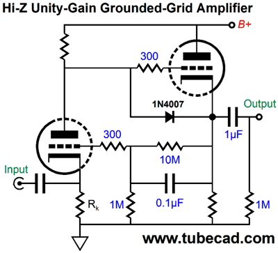
We can make a trade that will give us both lower distortion and lower output impedance and a relatively higher input impedance. So what must we trade away? Voltage gain is the answer. If we add a negative feedback loop, using the grounded-grid amplifier's grid as the inverting input. At one extreme, the entire circuit would become a unity-gain buffer, offering no voltage gain, but a very-low output impedance.
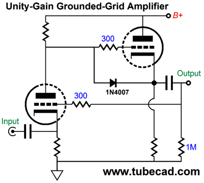
Since the grounded-grid amplifier does not invert the input signal, the output signal at its plate is in phase with the input signal, which is then passed off to the cathode follower, which, in turn, delivers the in-phase signal to the grounded-grid amplifier's grid. The net result is a tiny signal insertion loss, say as little as -0.1dB; a very-low output impedance, say below 10 ohms; and an input impedance just a tad lower than the grounded-grid amplifier's cathode resistor value. If this input impedance is still too high, which it could easily be, then the following variation is useful.
This variation allows us to use a much larger cathode resistor, which could be as high as 30k in value. By the way, the assumption here is that the grounded-grid amplifier triode is a high-mu, high-rp type, such as the 6SL7, 12AX7, 12AY7, 5751, and 6072, while the cathode follower triode is a low-mu, low-rp type, such as the 6AQ8, 6DJ8, 6CG7, 6SN7, 12AU7, 12BH7, 5687, and ECC99. In the 12DW7, we get dissimilar triodes, one 12AX7 and one 12AU7 triode, which is convenient.
The next step is a step away from 100% negative feedback towards partial negative feedback, which will develop some voltage gain. As a design example, let's use the 12DW7.
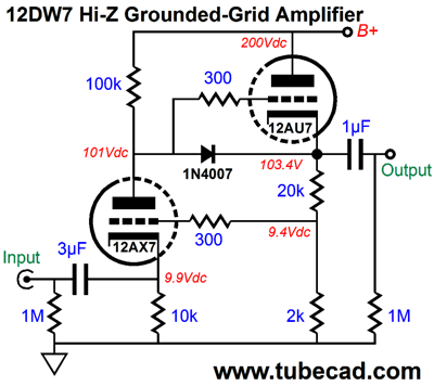
Note both the 3µF input coupling capacitor and the grounded-grid amplifier's 10k cathode resistor. The voltage gain comes in at about +19dB and the output impedance is a low 70 ohms. Not bad, from a 12AU7-based cathode follower.
We can replace the grounded-grid amplifier's cathode resistor with a constant-current source.
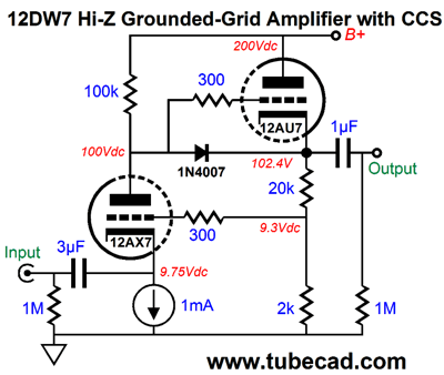
The constant-current source would not, however, raise the input impedance as much as it would in the unity-gain buffer design, so we are still stuck with the 3µF input coupling capacitor. Indeed, I much prefer the cathode-resistor-based version, as it scales beautifully up and down with varying B+ voltage, which the constant-current source would not. In other words, with the cathode resistor, the B+ voltage can be increased to +300Vdc and the grounded-grid amplifier's plate voltage will center at about 150Vdc; in contrast, with the constant-current source, the plate voltage would rise to exactly 200Vdc, stealing cathode-to-plate voltage from the cathode follower and making the heater reference voltage dangerously high at 100Vdc.
What happens if we replace both the grounded-grid amplifier's plate resistor and the cathode follower's cathode resistor with active loads? Well, we get something like this:
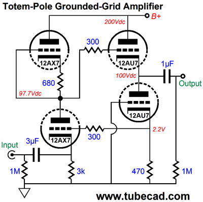
(Let me interrupt this tutorial by gratuitously and shamelessly stating that what I like best about this topology is that only I would ever come up with it.)
No SRPP is contained herein, as nothing pushes or pulls—only single-ended action as far as the scope can display. But, John, don't you see that one triode sits atop another, which is what occurs in an SRPP? Yes, I see it clearly, but SRPP does not just mean that one triode sits atop another. What is important is how the circuit works internally, which in this circuit is in an entirely non-SRPP fashion.
In an SRPP, the load impedance is a critical aspect of the design. Indeed, if there no external load, the SRPP becomes the SRSE, as both triodes conduct current in phase, no longer in anti-phase, so no push-pull operation. In the circuit shown above, the input stage is effectively not loaded by the second stage, and the first stage's output is taken at the bottom 12AX7's plate, not the top 12AX7's cathode, so the 680-ohm resistor is merely a cathode resistor, not a current-sense resistor. In other words, no SRPP, as there is no push-pull operation. Put differently, there is no SRPP, as there is no current delta between top and bottom 12AX7 triodes. In sum, no SRPP.
This grounded-grid amplifier simply uses an active plate load, which could be replaced by a resistor. The top 12AX7 defines an active load resistance equal to rp + (mu + 1)680. The bottom 12AU7 defines an active load resistance equal to rp + (mu + 1)470. The negative feedback attaches at the bottom 12AU7's cathode resistor. Since a smaller sampling of the output signal is present at the top of the cathode resistor, less negative feedback is applied, which results in a high voltage gain, which could prove useful in some applications.
Long-time readers will recognize the following topology, as I have shown it many times before. The idea is a simple one: we use the grounded-grid amplifier's grid as an inverting input and feed it a sampling of the power-supply noise, so we can create a null at the grounded-grid amplifier's output.
Note how only one triode is needed, not the four that are used in my grounded-cathode amplifier based Aikido circuit. Resistors R1 & R2 define a two-resistor voltage divider that delivers the correct portion of the power-supply noise to the grid. The capacitor that attaches to the B+ connection shields the voltage divider from the high voltage. No input coupling capacitor is shown, but one would probably be needed in actual use. In fact, in actual use, more would be needed to make a useful line-stage amplifier, such as cathode follower output stage.
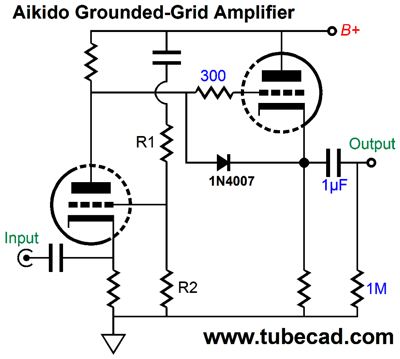
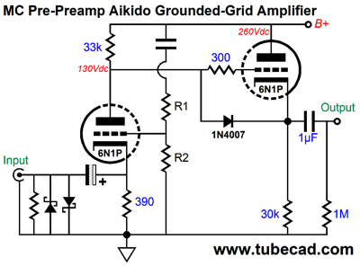
Here we see a more fleshed out Aikido grounded-grid amplifier. The 1N4007 safety diode is in place and the cathode follower offers a low output impedance, while shielding the grounded-grid amplifier from the external load impedance. The resistor values for the two-resistor voltage divider depends on the input triode used.
Now let's get extra fancy. How about eliminating the input coupling capacitor, is that possible? Sure it is; we just need to use a negative power-supply rail and a DC servo to keep the grounded-grid amplifier's input at ground potential.
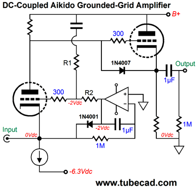
Where to start? The 6.3Vdc negative power-supply rail allows us to supply both the constant-current source and possibly the tube's heater. If a 6DJ8 is used, and if a low B+ voltage is used, say 150Vdc, then we can probably get away with it, as the cathode follower's cathode will not be at too high a voltage to exceed the cathode-to-heater maximum voltage. The DC servo monitors the input DC offset and constantly makes small adjustments to its output voltage to keep the input centered at 0Vdc. At the same time the two-resistor voltage divider terminates into the DC servo's output, which in audio frequency AC terms is the same as ground. The 1N4001 diode is a safety device that is normally reversed biased and falls out of the circuit. But at startup, when the input triode is still cold, the diode becomes forward biased and conducts, allowing the DC servo to pull against the constant-current source and bring the input up to 0Vdc. As long as the input sign does not swing below about -2.7V, in this example, the diode will not be a problem.
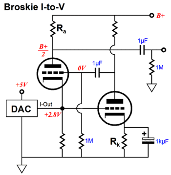
I know that many are thinking that this circuit would be ideal to connect to a DAC's current-output. Well, actually, it would work better with a voltage-out DAC, as the input impedance, while low, is not low enough. For a current-out DAC, the Broskie I-to-V converter is a better choice.
Since we are in a fancy mood, why not design an MC phono pre-preamp? A moving-coil phono cartridge requires a low-impedance shunting resistance, sometimes as little as 100 ohms. So, here is an example of where the grounded-grid amplifier's low input impedance can become a virtue, not a liability.
Once again, where to start? The unmarked resistor can be whatever value is needed to work in parallel with the 390-ohm cathode resistor for loading the cartridge. The two funny looking diodes are Schottky diodes, which unlike the typical rectifier diode are super-fast and offer a very low forward voltage drop, which will prove helpful in protecting the delicate MC from the coupling capacitor discharge at turn off. Speaking of the coupling capacitor, I would actually use a non-polarized Panasonic capacitor, not the electrolytic capacitor shown. The cathode follower stage may not be needed at all, as the typical moving-magnet phono preamp resents an input impedance of 47k.
What if we want to use the grounded-grid amplifier with a step-up transformer? First of all, the transformer must be able to sustain a DC current flow through its secondary, as all of the triode's current must flow through the secondary. In addition, the secondary is not likely to present enough DCR to bias the triode correctly.
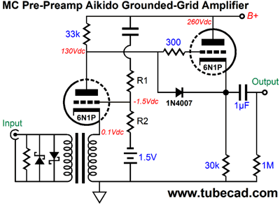
The workaround shown above will trouble many readers, so I will down shift a gear or two. Since the secondary DC resistance is too low to bias the triode, we must make the grid more negative than the cathode by some other means. The battery provides the negative bias voltage needed. Wait a minute, John, batteries wear out and are a pain to replace and expensive. Audio playback requires linear electronics, which is a tad ironic, as most audiophiles are nonlinear thinkers. I know many audiophiles, who think nothing of buying a new $5,000 phono cartridge every other year, but complain and whine about the expense and hassle of replacing a battery every ten years. Ten years? Yes, ten years, which is the average shelf-life of the typical high-quality, alkaline battery. In this circuit, the battery does not deliver any DC current, acting only as a self-powered voltage reference. In other words, the battery is not used in any real sense, so its output voltage is roughly equal to its published shelf-life. (The only real use occurs at turn-on and turn-off, as the capacitor that attaches to the the two-resistor voltage divider must first charge up and then then discharge; that's it.)
If you are wondering why the two Schottky diodes are used, particularly as the transformer shields the MC cartridge from the cathode voltage, the answer is that at shut-off, the transformer can develop a voltage pulse at the primary, which the Schottky diodes will shunt to ground.
While we are still feeling fancy, let's design a four-triode Aikido grounded-grid amplifier.
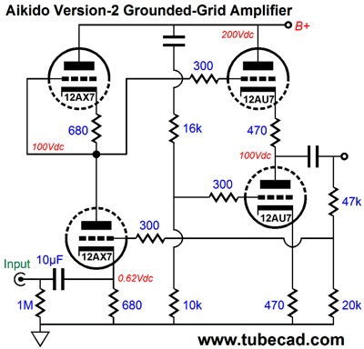
Much like the typical Aikido line-stage amplifier, this design uses two tubes and four triodes. A negative feedback loop attaches after the output coupling capacitor, which allows easy adjustment of the feedback ratio. From here, it's a small step to an Aikido push-pull grounded-grid amplifier for driving headphones.
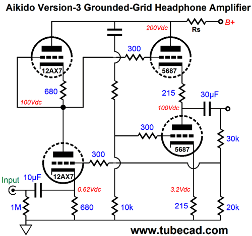
We have added a current-sense resistor, Rs; and we are using a much larger valued output coupling capacitor. The intended load impedance is 300 ohms and lower gain is established by the feedback ratio resistors. The 5687 output tube idles at a hot 15mA and can deliver twice that current into the high-impedance headphones. It is a push-pull, class-A output stage after all. The unmarked resistor's value would have to be found either through some complex math or via SPICE simulations or actual hands-on testing in reality with the real grounded-grid amplifier.
Okay, one last circuit: a balanced Aikido grounded-grid amplifier:
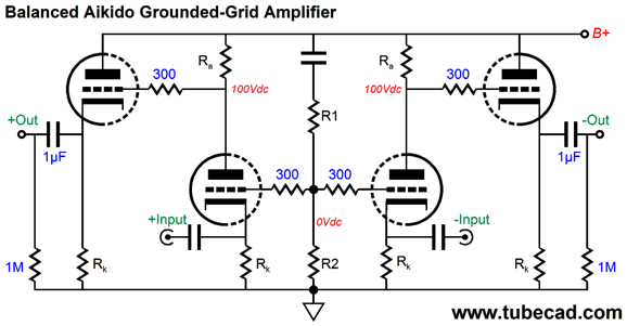
Note how the two-resistor voltage divider is shared by both input triodes. Also note that with certain signal source, the two input coupling capacitors could be eliminated, as the the two cathode inputs should be at roughly the same value.
Before ending, I must point out that all of these Aikido grounded-grid amplifier designs assume that a low-impedance signal source is used and that no intervening resistance is added, such as a volume potentiometer would add.
One problem with the above circuit is that it presents a poor CCRR, which is really what balanced circuit are all about. We must cross-couple the input grounded-grid amplifiers to get an improved CMRR.
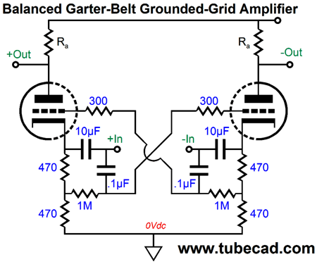
The above circuit offers a much improved CMRR, but a much poorer PSRR, so we must chose which is more important. To see how the CMRR obtains, imagine the same, in phase, signal being applied to both inputs. All the cathodes and grid would see the same signal, which would greatly reduce the gain realized. Another problem with this circuit is that it not really a grounded-grid amplifier. It is, in fact, a hybrid between the grounded-grid amplifier and the grounded-cathode amplifier. Indeed, other than increased gain, we seem to have gotten the worst of both worlds: low input impedance and Miller-effect capacitance. The next circuit offers a better solution.
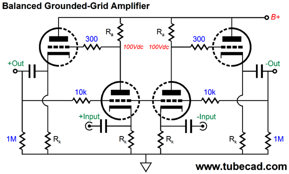
This balanced grounded-grid amplifier delivers both a fine CMRR and stellar PSRR. Actually, the stellar PSRR figure is the result of the fine CMRR, as any power-supply noise that leaks into the output will be equal and common to both outputs, so both input triodes see the same unwanted signal strive to eliminate it. The CMRR is interesting. If the same, in-phase, input signal is presented to both input cathodes, the output gain will be 1 (or unity or 0dB). Thus, the CMRR will equal 20Log(1/gain) in dBs.
All that is really missing is two 1N4007 safety diodes. What could this circuit be used for? Most standalone DACs offer balanced outputs along with the RCA jacks. The balanced outputs could drive this balanced grounded-grid amplifier, which in turn would drive a power amplifier with balanced inputs.


회원에게만 댓글 작성 권한이 있습니다.